Other Auto Part,Other Car Accessories,Auto Parts Near Me,Auto Part Ningbo Maixun International Trade Co., Ltd , https://www.maixuncarparts.com
Turbine DEH low-voltage pure electric control system consists of two parts: electrical and EH hydraulic system. The electrical part adopts the DEH digital controller. The EH hydraulic system part includes the oil supply system, servo system and security system. Because the servo system actuator adopts low-pressure turbine oil as the working medium, this low-voltage pure electric control is not only equipped with the newly-manufactured steam turbine of the steam turbine plant, but also the modification of the regulating system of the old unit steam turbine, and its oil supply system, oil motive, and steam distribution mechanism And the security system still uses conventional equipment without any changes. It is mainly how to configure the electrohydraulic converter and some accessory components for the oil motive. Therefore, the steam turbine adopts low-voltage pure electric regulation, which makes the hydraulic adjustment part relatively simple, easy to transform, simple in operation and maintenance, and the production cost and operation and maintenance costs are relatively low. Therefore, the low-voltage turbine oil pure electric adjustment is generally applicable to 125MW and 100MW. Medium and small capacity units such as 50MW and 25MW are used.
Starting from 1999, Xinhua Company developed a low-voltage turbine oil pure electro-hydraulic system using a torque motor disc-type electro-hydraulic converter as the electro-hydraulic interface in order to meet the needs of the electricity market. Up to now, the 135MW and 6MW, 50MW, 100MW, 125MW, 350MW and other old turbines that have been newly produced at SAIC have been applied to a total of 37 steam turbines of various types and have received good results. At the same time, at the request of users, we also deployed a low-voltage turbine oil pure electro-hydraulic system with DDV servo valves as the electro-hydraulic interface for 11 units of various types.
As we all know, the key component of the pure ESC of low-pressure turbine oil is the electro-hydraulic converter. The valve structure of the torque motor is adopted by Xinhua, and the torque motor is applied to the product of the American company BRIEN. The structure is simple and the dynamic response performance is good. Because the control port of this electro-hydraulic converter adopts a disc valve type structure, the requirement for oil quality is not demanding, and it can adapt to the general cleanliness level of the turbine oil system, and absolutely no jam phenomenon will occur. Operational tests prove that its performance is good and its use is safe and reliable. Due to its excellent performance, it has opened up a bright future for the development and application of low-voltage turbine oil pure electric modulation.
Xinhua Company now has A-type and B-type disk-valve type electro-hydraulic converters. Type A is equipped with a steam-type oil pump. Type B can be used to directly control a Kazakhstan-type gas oil pump without configuring an intermediate control slide valve. Therefore, any type of steam turbine can be used with DEH low-pressure turbine oil pure electro-adjustment system.
Second, the characteristics of low-voltage turbine oil pure electric tune Low-pressure turbine oil pure electro-adjustment system's main features are as follows:
2.1 The regulation system adopts DEH digital controller, and the controller is basically the same as high-voltage anti-fuel pure electro-adjustment system.
2.2 Oil Turbine The low-pressure turbine oil is used to supply oil from the unit's fuel supply system. No separate oil supply device is required.
2.3 electro-hydraulic conversion element using torque motor disc valve type electro-hydraulic converter, high control accuracy, dynamic response performance, no sliding valve stuck parts, good resistance to oil pollution.
2.4 The oil motive and the steam distribution mechanism connected with the valve can maintain the original structure, and the transformation is convenient and the manufacturing cost is low.
2.5 Valve management part: For a unit with one valve for a oil motive, DEH low-pressure turbine oil pure electro-adjusting system for Shangqi 135MW unit, which can realize the valve management function, including linearization, single/multi-valve mode, single/ Multi-valve switching. For a unit with two valves for a petrol engine, such as a 125MW steam turbine, and an oil motive unit that drives four steam regulating valves through a cam distribution mechanism, such as the 50MW and 100MW steam turbines of Kazakhstan Steam Plant and North Heavy Plant. Pure electro-adjustment system, adjusting steam valve is still opened one by one according to the order of the original mechanical setting, nozzle control mode is used to control the unit operation, and the computer completes the linearization process.
2.6 The system has the function of power failure protection. When the DEH loses power, and the electro-hydraulic converter has no electric signal input, the moment motor torque is zero, and the hydraulic pressure output of the electro-hydraulic converter falls to the minimum, so that the oil engine is shut down and the unit is shut down. Security.
2.7 system uses LVDT oil-driven position feedback loop, the servo system of the delay rate is small, high positioning accuracy, can effectively overcome various internal disturbances in the servo loop, improve the stability of the entire system and control accuracy.
Third, the electro-hydraulic converter 3.1 Electro-hydraulic converter performance structure Low-pressure turbine oil Pure electric torque used by the motor disk valve electro-hydraulic converter as shown in Figure 1 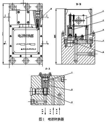
An electro-hydraulic converter is a conversion amplifying element that converts an electrical signal into a hydraulic signal. It is a precision critical component in an electrical regulation system. The electro-hydraulic converter adopts a torque motor disc valve amplification structure and is mainly composed of a torque motor 1, a spring 2, a lever assembly 3, a disc valve 4, a damper 5, an orifice 6 and a housing.
A downward force of the torque motor 1 and the spring 2 acts on the lever assembly 3, and an upward force of the oil pressure PE acting on the butterfly valve 4 is controlled. Electric pressure control hydraulic pressure PE is formed by the pressure oil flowing through the orifice through the gap after the disk valve 4 oil. When the current signal from the DEH controller is sent to the control coil of the torque motor, the torque produced by the magnetic field of the permanent magnet causes the torque motor to change angles, and the force is applied to the lever assembly 3 via the ejector rod, thereby changing the The gap of the butterfly valve changes the control hydraulic pressure PE. When the input current signal increases, the force of the torque motor increases, the disc valve clearance decreases, so that the PE hydraulic pressure increases; conversely when the input current signal decreases, the torque motor force decreases, the disc valve clearance increases, Then the electric pressure control PE will be reduced. Thus, the opening degree of the steam valve is adjusted by the oil motor control to open or close small.
By adjusting the screw to change the pretension of the spring 2, the initial value of the control oil pressure PE can be changed. The damper 5 stabilizes the oil pressure.
In addition, a critical relay is also provided in the electro-hydraulic converter, which consists of a piston 7, a sleeve 8, a compression spring 9, and the like. The safety oil is applied to the upper part of the critical relay piston 7 and the lower part is controlled by the hydraulic pressure PE. When the steam turbine evacuates the safety oil during emergency or normal shutdown, the piston moves upwards under the action of the spring force, opening the disc valve drain port at the lower part of the piston, so that the control oil leaks out, so that the regulating steam valve and the main steam valve are rapidly closed at the same time. And stop.
3.2 Commissioning of electro-hydraulic converter For the debugging of electro-hydraulic converter, the relationship between the torque motor input current I and the electro-hydraulic converter output control oil pressure PE is mainly determined, and the insensitivity size is determined.
3.2.1A type electro-hydraulic converter working oil pressure P = 0.8 ~ 2.0Mpa
Turbine oil temperature t=40±5°C
The debugging method is as follows:
(1) The two sets of coils of the torque motor are connected in parallel, and a 0-400mA adjustable analog current signal is input.
(2) When the input current I = 0, adjust the top rod of the torque motor, and when fully released, adjust the spring upper screw. Change the pre-compression force of the spring so that the output control oil pressure PE = 0.05 MPa. After adjustment, tighten the screw.
(3) Then adjust the torque motor top rod so that the output oil pressure rises to about PE = 0.07 MPa. After reaching the required value, the top rod is tightened with the lock nut.
(4) Change the input current from 0 to 400mA, change every interval of a certain value, and record the change of the corresponding PE oil pressure from 0.07 to 0.4MPa. Repeat once and again. Or pressure the pressure transmitter and measure the I-PE characteristic curve with an X-Y recorder.
(5) I-PE characteristic curve was compiled according to the test record, and the insensitivity ε ≤ 2% was calculated. Characteristic curve is shown as in Fig. 2. 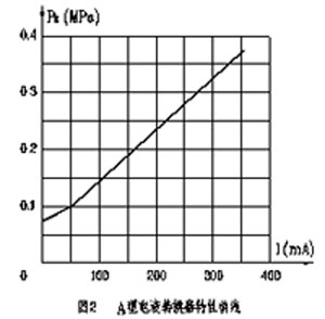
3.2.2B type electro-hydraulic converter working oil pressure P=1.5~2.2Mpa
Turbine oil temperature t=40±5°C
The debugging method is as follows:
(1) The two sets of coils of the torque motor are connected in parallel, and a 0-250mA adjustable analog current signal is input.
(2) When the input current I = 0, adjust the top rod of the torque motor, and when fully released, adjust the spring upper screw. Change the pre-compression force of the spring so that the output control oil pressure is equal to 0.5 MPa. After adjustment, tighten the screw.
(3) Then adjust the torque motor jack so that the output oil pressure rises to about PE = 0.6MPa. After reaching the required value, the jack is tightened with the lock nut.
(4) change the input current from 0 ~ 250mA, every interval of a certain value changes, record the corresponding PE hydraulic pressure change value from 0.6 ~ 1.2MPa or so. Repeat once and again. Or pressure the pressure transmitter and measure the I-PE characteristic curve with an X-Y recorder. When the PE is 1.0 MPa, the corresponding current is about 150 mA.
(5) I-PE characteristic curve was compiled according to the test record, and the insensitivity ε ≤ 2% was calculated. The characteristic curve is shown in Figure 3. 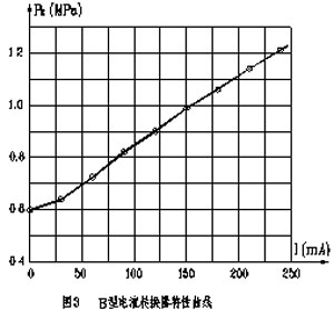
Electro-hydraulic converters and oil motives have a one-to-one configuration. Therefore, a total of 4 electro-hydraulic converters were installed on the unit and assembled into a regulating device. The servo control system for four oil motives is exactly the same, and the block diagram of its working principle is shown in Figure 4. 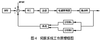
Servo control system consists of valve servo control card, power amplifier card, electro-hydraulic converter, oil motor, LVDT and other components. The DEH-IIIA controller processes the rotational speed, power, regulation pressure and other status information of the turbine generator set and outputs the opening command signal of each valve position. After the valve is servo-controlled, the power is amplified to control the electrohydraulic. Converter, the electro-hydraulic converter converts the electrical signal into a corresponding control oil pressure signal. This oil pressure is sent to the corresponding oil motive to accurately control the opening degree of each valve, thereby changing the rotation speed or power of the unit.
In order to improve the reliability of the control system, two LVDT displacement sensors are installed on each oil engine and are added as negative feedback signals and valve position command signals after high selection. Because the polarity of the two is opposite, the actual subtraction, when the signal input to the power amplifier after the valve position command signal and the LVDT feedback signal is added is zero, the output of the power amplifier is maintained at a certain value, and the oil engine stops moving and keeps In a new equilibrium position.
In the power amplifier is equipped with PI adjustment element, can carry on PI correction to the system, the parameter is variable. The power amplifier board input is 0 ~ 40mA (or 5V), and the amplified and corrected output current is 0 ~ 400mA to drive the torque motor. Electro-hydraulic converter input current in the torque motor is 0 ~ 400mA, and its output control oil pressure is 0.07 ~ 0.4MPa.
(2) The main points of adjustment of the regulation system are as follows:
1 Add DEH-IIIA controller (including engineer station, operator station), cancel rotary damping, amplifier, synchronizer, hydraulic converter, etc.
2 Add 4 electro-hydraulic converters to make one-to-one configuration with 4 high and medium pressure oil motives in the original regulation system.
3 Add 4 critical relays to allow the safety oil to act, and then control the oil by displacing the electro-hydraulic converter to shut down the oil motive.
4 Each oil motive is equipped with an overspeed protection control OPC double solenoid valve. When the turbine speed exceeds 103% nH, the OPC command signal from DEH will be immediately shut off to adjust the steam valve, which will inhibit the speed from flying up and prevent dynamic overspeed. And automatically control the unit to run at 3000r/min.
5 Add 2 displacement sensors for each oil motive to use as displacement feedback.
6 Add a gated solenoid valve, and make partial improvements to the original starting valve, so that the turbine can be remotely reset and open the main valve.
7 Add 2 safety oil pressure switches, switch signal send DEH, for interlock protection.
8 Add a dual-tube oil filter to improve the cleanliness of the oil supply to the electro-hydraulic converter.
9 Install a 10L accumulator on the pressure oil supply line of the electro-hydraulic converter to stabilize the oil pressure.
10 Set the adjustment device. Integrated by 4 electro-hydraulic converters, oil filters, accumulators, globe valves, pressure gauges, etc.
After the transformation of low-voltage pure electric control system shown in Figure 5 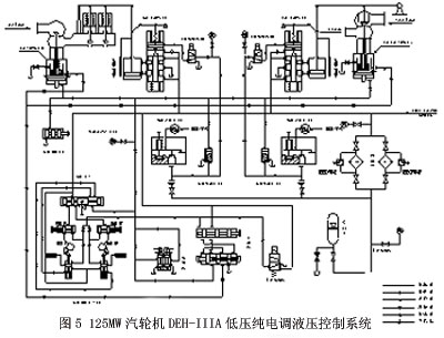
This reform program has been applied to SAIC's five 125MW units. The principle of servo system design can be applied to various types of turbines such as 12MW, 50MW, and 135MW produced by SAIC. Electro-hydraulic converters use type A and one-on-one configurations with oil motives.
In addition, the electro-hydraulic converter and the oil motor can also be used in a one-to-two configuration, that is, using an electro-hydraulic converter to control two oil motives at the same time. For example, the low-voltage turbine oil pure electro-adjustment system transformed by Baosteel's self-provided power plant 2 350MW units. The working principle of the servo control system is the same as the previous one. The difference is that the servo control system does not adopt the position feedback of the oil engine LVDT. Instead, a pressure transmitter is added to the output control of the electro-hydraulic converter and the hydraulic pressure feedback is used.
4.2100MW Turbine Low Pressure Turbine Oil N100-90/535 100MW Condensing Steam Turbine produced by Harbin Electric Plant. The turbine's control system uses a high-speed spring-type governor. There is an automatic shut-off device that is controlled by a safety oil. Four steam-adjusting valves are driven by an oil engine through a cam-operating valve mechanism. The oil pump adopts hydraulic pressure-return feedback on both sides and the power oil pressure is 2.0 MPa.
Low pressure turbine oil pure electric adjustment system as shown in Figure 6 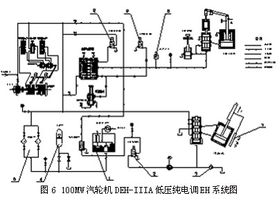
(1) The main points of adjustment of the regulation system are as follows:
1 Remove the governor, follow the wrong throttle, and allocate the wrong throttle, synchronizer, differentiator, overspeed limit slide valve and other parts.
2 Remove the crude oil motivation feedback valve and feedback lever.
3 Add DEH controller (including engineer station, operator station).
4 add a B-type electro-hydraulic converter, the output of oil pressure directly control the oil motive.
5 equipped with overspeed protection control OPC solenoid valve.
6 Install dual redundant LVDTs on the oil motive as feedback positioning.
7 Pressure regulators and accumulators are installed on the pressure fluid of the power supply converter.
8 Increase the brake solenoid valve and two safety oil pressure switches.
9 Retain the original shutoff solenoid valve, and additionally add dual redundant AST solenoid valves to improve safety and reliability.
10Add adjustable flow valve to adjust the offset of oil accelerator.
(11) Add three-way switch valve for pulsating oil switching test.
(2) Servo Control System Operation Principle The servo mechanism principle is shown in Figure 7. 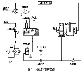
Emergency relays are installed in the electro-hydraulic converters. When an emergency shutdown occurs due to a fault in the turbine, the safety oil system will act, causing the critical relay to operate, draining off the pulsating oil and allowing the oil motor to act quickly to close the corresponding valve.
When the turbine speed exceeds 103% nH, the OPC command signal from the DEH is accepted, the OPC solenoid valve is actuated, and the pulsating oil is shut off and drained, and the regulating steam valve is immediately closed to prevent dynamic overspeed.
(3) Static adjustment of oil motive 1 Use a three-way switching valve to cut off the oil motive power pulsation circuit. 2 Debug according to Section 3.2.2 Type B Electro-hydraulic Converter Debugging Method in this PART, and make the following requirements:
Working oil pressure P=2.0MPa
Input current I=150mA
Control hydraulic pressure PE = about 1.0MPa 3 Then use a three-way switching valve to cut off the control hydraulic pressure output from the electro-hydraulic converter.
4 Adjust the adjustable flow valve so that the oil pressure is pulsating and the oil drive is in the closed position.
5 Restore the normal working position of the three-way valve.
6 Adjust the initial value of the power amplifier (about 150mA), so that the PE is 1.0MPa.
7 servo system closed-loop test.
Static and dynamic debugging of the servo system.
The design principle of the servo control system of this program is also applicable to the use of hydraulic feedback for crude oil motives. When the pulsating hydraulic pressure is in the steady state, the main oil pump is half the hydraulic pressure of the unit, such as Kazakhstan Auto, Dongqi, Beizhong, Wuxi, Nanqi, etc. Manufacturers of 25MW, 50MW, 100MW and other types of steam turbines. In the EH system, the electro-hydraulic converter adopts type B, and the oil motive adopts one-to-one configuration.
Fifth, the use of DDV valve low-pressure turbine oil pure electric adjustment 5.1DDV servo valve structure principle DDV valve structure shown in Figure 8: 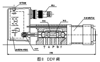
The DDV servo valve is a direct-drive electro-hydraulic servo valve recently introduced by MOOG of the United States, abbreviated as DDV (abbreviation of DirectDriveServoValve).
It is mainly composed of valve position controller (integrated electronic circuit), displacement sensor, valve sleeve, valve core, linear motor (including the middle spring) and so on. When an electrical command signal is applied to the spool position controller manifold, this electrical signal is converted to a pulse width modulated (PWM) current and the oscillator excites the spool position sensor (LVDT). The demodulated spool position signal is compared with the command position signal, so that the spool position controller generates a current to the force motor, which drives the spool and moves the spool to a new equilibrium position. The position of the spool is proportional to the command signal. The actual flow Q of the servo valve is a function of the position of the spool and the pressure drop across the metering edge of the spool.
The DDV valve has five ports P, A, B, T, and Y. A and B are flow control ports (throttle ports) controlled by the spool. P is connected to pressure oil, and T and Y are oil return ports. According to different connections, it can constitute the function of the slide valve: two-position two-way, three-way, four-way.
Valve maximum flow 85L/min
Maximum working pressure 35MPa
Controller power supply voltage 24VDC
Command signal ±10mA, +4 to +20mA
The cleanliness requirements of NAS are not less than 6-level DDV servo valve features:
â—Using high-energy permanent magnet linear motors, with self-amplification, large driving force.
â— When the power is cut off, the cable is damaged, or the machine is stopped in an emergency, the servo valve can return to its own position without external force.
â— The dynamic response is high, and the dynamic performance index is independent of the supply pressure.
â— Low hysteresis and high resolution allow the system to have excellent repeatability.
â— With reverse polarity protection and overvoltage protection.
â— Electronic zero adjustment to compensate for load drift.
5.2 DDV Valve Electrohydraulic Servo Control System The operation principle of the DDV valve electrohydraulic servo system applied to the HCV type oil motor is shown in Figure 9. 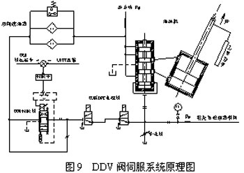
The valve command signal issued by the DEH is amplified by the servo amplifier, and the DDV valve converts the electrical signal into a pulsating hydraulic signal. The direct control of the oil motor drives the regulating valve to change the unit's rotational speed or power. When the oil motive moves, the LVDT displacement sensor is driven and added as the negative feedback signal and the valve position command signal. When the two electric signals are balanced, the output of the servo amplifier keeps the original steady state value. At this moment, the DDV valve returns to the original equilibrium position, keeps the pulsating oil pressure value unchanged, and the oil motive stabilizes in a new job. position. The OPC solenoid valve in the system is provided for overspeed protection. The adjustable flow valve is used to adjust the offset of the oil accelerator's wrong throttle.
5.3 Usage In order to meet the requirements of users, Xinhua Company has designed a low-voltage turbine oil pure electro-adjustment system using DDV valves as electro-hydraulic interface components. It has been used in Maanshan Power Plant 12MW, Handan Power Plant 25MW, Baling Petrochemical 50MW, etc. The transformation. The operating conditions so far have been satisfactory.
After using and analyzing the system, we believe that the following problems still exist:
(1) The DDV valve is a high-pressure series servo valve produced by MOOG. The clearance between the valve plug and the valve sleeve is only about 2~3μ. Therefore, the cleanliness of the turbine oil should be no less than 6 degrees when using, otherwise it will be Squeeze occurs in the spool, because the turbine unit is a pet system that leads to the entire unit. Many places are open, in contact with the air, and sometimes seeps into the steam, water, etc. The oil is susceptible to ageing and deterioration, and fine foreign particles are also easily accessible, so it is difficult to maintain a good level of cleanliness of the turbine oil, which will ultimately affect the normal operation of the DDV valve.
(2) For the DDV valve control system configured for oil engines with oscillating oil pressure and constant oil pressure, the DDV valve is in the neutral position in the steady state, and there is no one-to-one correspondence between the displacement of the oil motor and the position of the DDV valve, and therefore the adjustment is During the process, once the DDV valve fails to return to the equilibrium position, the oil motive will go until it is fully open or fully closed, which will endanger the safe operation of the unit.
For this reason, in the future, in addition to the special requirements of power plants using DDV valves, DDV valves are generally not recommended as pure electro-hydraulic for low pressure turbine oils for electro-hydraulic interface components.
Sixth, concluding remarks The electro-hydraulic converter of the torque motor valve type structure without sliding valve mechanism designed and developed by Xinhua Company has high anti-pollution capability, no jamming phenomenon, and can be operated stably in general conventional lubricant oil systems. It is especially suitable for the hydraulic control system of medium and small units. Practice has proved that the adoption of Xinhua's DEH low-pressure turbine oil pure electric adjustment unit, have achieved good results, the unit running stable, safe and reliable.
I. Overview The steam turbine is equipped with a DEH digital controller. The pure ESC system that uses the low-pressure turbine oil (general oil pressure 1.0~2.0 MPa) as the power to drive the steam valve actuator is called the low-voltage turbine oil pure ESC system. IV. Low-pressure Turbine Oil Pure Electric Control System 4.1125MW Turbine Low-pressure Turbine Oil Pure Electric Adjustment (1) Working principle of servo control system 125MW intermediate reheat turbine has two high-pressure main valves and two medium-pressure main valves. The control seat for controlling the high and medium pressure main valves is a switch-type direct-acting type and is controlled by the safety oil pressure. There are 4 high-pressure steam regulating valves. The transmission mechanism is lever lift type. Steam valves I, IV and II and III are each operated by an oil motor. The opening sequence of each valve is controlled by the elliptical hole in the upper part of the door. The two medium-pressure regulating steam valves are also driven by a medium-pressure oil engine through levers. The high and medium pressure regulating steam valves and the corresponding oil motives are symmetrically arranged on the left and right sides of the high and medium pressure cylinders, respectively. After the computer operation and processing of the valve position signal is amplified by the servo amplifier, the input electro-hydraulic converter converts the electrical signal into a hydraulic signal, and the hydraulic pulsation oil pressure signal controls the piston movement of the oil engine. When the piston moves, the LVDT displacement sensor is driven. The mechanical displacement of the oil motor is converted into an electrical signal, which is added as the negative feedback signal and the DEH valve position command signal. When the signal of the input servo amplifier is zero, the output of the servo amplifier maintains the steady state value at this time. The oscillating oil pressure value output by the electro-hydraulic converter also maintains its original steady state value, and the oil engine stops moving and remains in a new working position.